


Metrum Newsletter - January 2024

A history of SPDIF and I2S digital audio interfaces
![]()
Introduction
New Year, new cycle around the sun, new chances..jpg)
New Metrum or Sonnet?
Finally! Snow outside of the Metrum Acoustics headquarters. Nature at its best! Temperatures dropped, and so did the prices on the combinations we talked about in our previous newsletter. You can own one of our no-nonsense audio products for a reduced price, that being a Metrum Jade for the price of an Onyx adding neutral volume control for free, or one of the selected Sonnet Digital Audio combinations with a 10% discount. Enjoy our true-to-nature sound, go out on a limb, but don't break a leg because „baby it's cold outside“! Our online headquarters is always open, regardless of snow: https://metrumacoustics.com
Click here to scroll to email-omitted details
A trip down memory lane
Now let's take a trip down memory lane... Back to the day when 14 bits were read off a silver disc and converted to 8 bits (Eight to Fourteen Modulation - EFM, not to confuse with EMF, which is quite "unbelievable"). Two times 8 bits made up for one 16-bit sample, for one audio channel. This was done to correct errors in the reading process of said CDs; certain sequences of bits were less prone to reading errors than others, while in the process making almost half of the bits on a CD redundant. Add interleaving CIRC coding to that and more than half of the data on a CD was redundant, at least now it was more resistant to reading errors due to debris or scratches. Great, we have the digital audio out!
For analog Music output to our analog amplifiers, Digital-to-Analog conversion was needed. The world had not seen a digital sound device yet, so a format was needed to internally transmit the 16-bit audio stream to the DAC chip(s). Several formats were introduced, because, well... why not have different formats that are not compatible? We saw 16 bits right justified (RJ16), left justified (LJ), RJ24, LJ24, EIAJ and also I2S.

„It's a kind of magic...“
I2S, one of the most magical beasts of the audio industry, is the Inter-IC-Sound interface that was invented after Sony and Philips started working on the silver disc player that saw its' life light around 1982. I2S consists of no less than 4 data lines that work in unison to deliver unadulterated bit-perfect digital data and is usually only used on the inside of audio equipment. No error correction is present in the interface bus, so the receiver must synchronize with the transmitter. Since the clocking is sent separately from the signal in I2S, no signal-induced jitter is introduced (debatable, but nonetheless an interesting experiment!).
SPDIF (Sony Philips Digital Interface), contrary to I2S, is used to transmit digital data between 2 pieces of audio equipment, where one is the sender (CD transport) and the other is the receiver (DAC). SPDIF sends a clock signal along with the data signal using bi-phase mark coding. To make the picture complete, SPDIF receiver chips all have I2S outputs, so SPDIF can be seen as an intermediary step to transmit digital audio signals from one audio device to another that eliminated complex and expensive cables (the CAT5 cable emerged in 1995!). A simple and cheap cable was needed for consumer use, so Toslink (1983) and Coax were employed. For professional use, the AES/EBU standard was implemented. Final fun fact is that SPDIF connections are limited to a 192kHz sampling rate (Toslink caters for 96kHz signals maximum).
Back to the current era...
Audiophiles require a high-speed digital audio interface that introduces as little jitter as possible. Every step or conversion can introduce unwanted jitter. Metrum Acoustics removed the encoding and decoding step that SPDIF introduces by using a direct I2S connection between the streamer and DAC. Doing so, it keeps everything simple and according to the KISS principle (Keep It Simple, Simmons!) This can be done if the impedance of the cable matches the impedance of the transmitter (streamer) and receiver (DAC). Otherwise, reflections are the result, resulting in more unwanted jitter. Not unimportant is that disturbances from the outside are kept away by shielding. This way, 384kHz or possibly even higher sampling rates can be transmitted via a "simple network cable". In the current day network cable is very cost-effective, readily available, as well as perfectly suitable for a beautiful I2S connection. Like Minnie Riperton, Metrum <3 I2S. „Loving you is easy“.
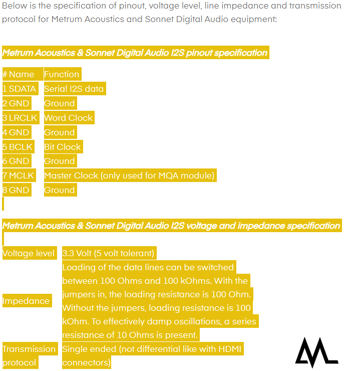
Wrapping this I2S story up, we wrote a practical article on how I2S is implemented in our audio devices and how to connect it to third-party hardware. As with the RJ, LJ, EIAJ and I2S story, the I2S connection is not standardized across manufacturers. You can find the connector style, which signals are connected to which pins, what their voltage level is and the impedance that is needed to match it. For customers that use Metrum and Sonnet streamers and DACs, it is a simple plug-and-play operation, even when using a Metrum Ambre streamer and a Sonnet Pasithea DAC or a Sonnet Hermes streamer and a Metrum Adagio DAC. You can find a screenshot below and the practical I2S documentation on our website: https://metrumacoustics.com/content/21-i2s-module. With this newsletter, we filled in a little background on how I2S things came to be and what some of the differences are between digital audio connections. Sometimes we are still amazed by how many 'standards' are out there and how far digital audio has come. Up to the next frontier!
For the Techies: I2S in depth
I2S is a ‘variation’ of the synchronous I2C bus, which is used to transfer audio data between chips on a circuit board (think of DAC chips), and it’s actually quite clever.
The I2S specification can be downloaded here and comprises the names of the signals, timing, voltage levels, and the order to send the bits. Three data lines are specified (where most I2S interfaces have 4 signals):
- Sample Clock (SCK, also called Bit Clock – BCLK) transitions with every bit sent
- Word Select (WS, also called Left Right Clock – LRCLK) transitions before sending data for one of the audio channels
- Serial Data (SD or SDATA) sends the audio data with the Most Significant Bit (MSB) first
The fourth signal, or Master Clock (MCLK) that can be found on most I2S devices is not described, but digital filters, oversamplers and DSPs usually need the MCLK to operate. The frequency of MCLK is a multiple of 44.1 or 48, multiplied by 32 (bits – yes, for the rest zeros are added), multiplied by 2 (channels). This means that source material that is sampled with 44100 Hz, has a resolution of 16 bits and is 2 channel stereo has a data rate of 44100 x 32 x 2 = 2822400 bps, that is 2.8 Mbps. Source material that is 384kHz then needs a data rate of 384000 x 32 x 2 = 24.576.000 bps, or 24.5 Mbps.
Unsurprisingly this happily coincides with the crystal oscillators that are present in our equipment, 22.5792 MHz and 24.576 MHz. These calculations also show the inner workings of the I2S interface. The MCLK is either 22.5792 or 24.576 Mhz, depending on the sample rate being played. The Bit Clock (BCLK) is derived from the MCLK by using a simple divider. By dividing by 64, the Left Right Clock (LRCLK) can also be derived. Did we say that I2S is actually quite clever already? It also requires practically no processing power.
Fun facts
The MSB is the sign bit of the 2’s complement encoded signal (so it indicates a positive or negative signal), the rest of the bits behind the MSB encode how high the musical signal is.
When the WS line (LRCLK) is low, the left audio channel is transmitted.
NXP Semiconductors was Philips in the old days (the P in S/PDIF).
The sender or receiver can be the ‘clock master’ (one at a time, not both); data always goes from sender to receiver.
The frequency of sampling is not specified, and no maximum sampling frequency is specified for data transfer.
The word ‘jitter’ is not mentioned in the I2S documentation.
Time keeping
So, what does an external word-clock do? It replaces the LRCLK with a cleaner (lower jitter) clock, or keeps various I2S/SPDIF sources in a recording studio in sync. To make sure that the MCLK and BCLK are synchronized to the word clock. However, well-built equipment has a clean clock on board and solves the jitter problem at the source.
In the audio industry, several connector styles can be used to make an I2S connection between devices. We mostly see RJ45 and HDMI connector formats, where RJ45 (a network plug) uses single ended signalling, and HDMI uses differential signalling (LVDS – mostly used for driving laptop screens).
An overview of the most used connector styles is available online. Frustratingly, there are several pinout specifications around the industry and they are not directly compatible. A break-out cable can help when two incompatible RJ45 devices are coupled. More information on coupling I2S devices can be found on our website under Technical Info > I2S Information. When HDMI equipment needs to be connected to RJ45 equipped devices, a chip is needed that ‘translates’ the Low Voltage Differential Signaling (LVDS) back to single ended first. Note: all chips with native I2S use a single ended connection style.
Keep listening to beautiful Music, we'll talk soon...

Team Metrum Acoustics